Overview
Bezier Curves and Surfaces
Bezier Curves with 1D de Casteljau Subdivision
Bezier Surfaces with Separable 1D de Casteljau
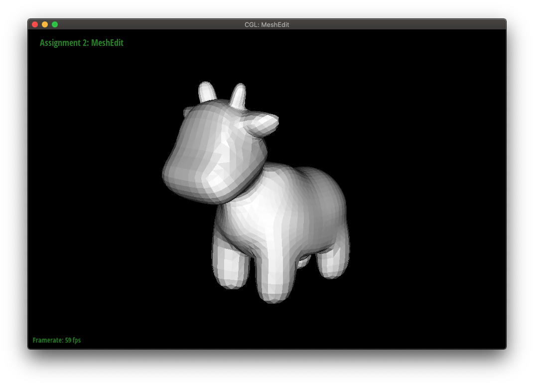
Triangle Meshes and Half-Edge Data Structure
Area-Weighted Vertex Normals
Edge Flip
Edge Split
Loop Subdivision for Mesh Upsampling
The goal of this project is to explore topics on geometric modeling, such as Bezier curves and triangle mesh manipulation using the half-edge data structure.
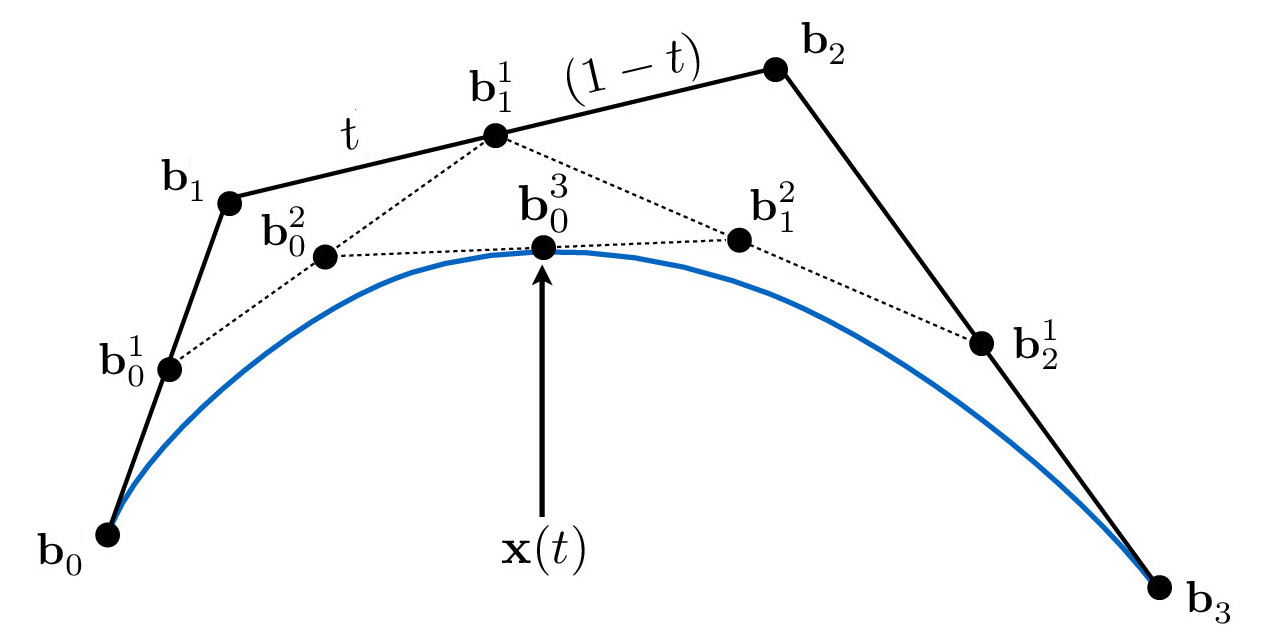
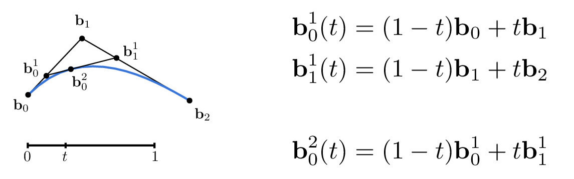
To evaluate Bezier curves, we can use de Casteljau's algorithm in which we recursively linearly interpolate between control points. More specifically, given a t-value, we can perform linear interpolations between adjacent control points until one point remains. This point lies on the Bezier curve, as illustrated in the Cubic Bezier Curve diagram below.
The following equations are used to evaluate the point at value t. This can be easily translated into code, and this is how I implemented the 1D Bezier curve function.
Credit: CS184/284A Lecture 7 Slides by Ren Ng
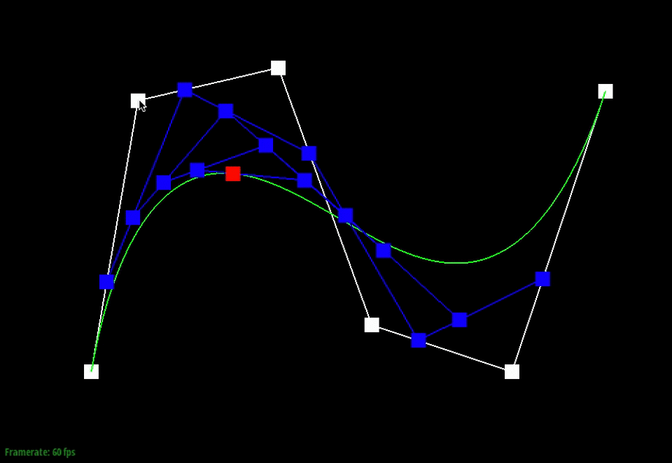
Below, the points in white are the original control points. The animation shows the intermediate points (blue) that are generated from the recursive interpolation steps and the point (red) that lies on the final Bezier curve (green) for one particular t-value.
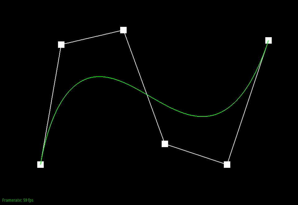
We can also visualize how the evaluated intermediate points change as we slide through the different t-values.
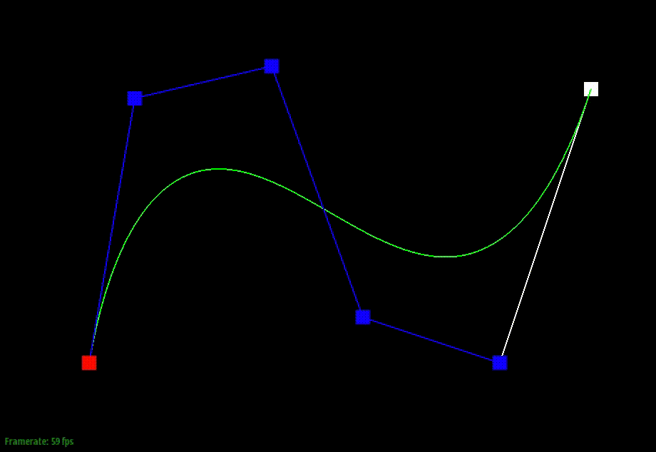
Moving the original control points will also affect the curve globally, as shown below.
The de Casteljau algorithm can also be extended to produce 3-dimensional surfaces. To produce a Bezier surface, multiple instances of de Casteljau's algorithm are performed. The details of this are described in the figure below.
Essentially, we want to calculate a (u, v) position on our surface by first calculating points of the curves in the u direction at the t-value v. These are then the control points of the "moving" curve, which we use to evaluate the final point at the t-value u.
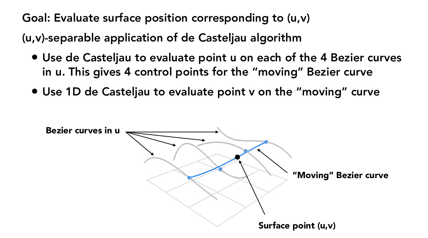
Credit: CS184/284A Lecture 7 Slides by Ren Ng
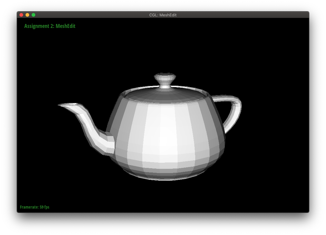
Using this method, we can create Bezier surfaces like the teapot below.

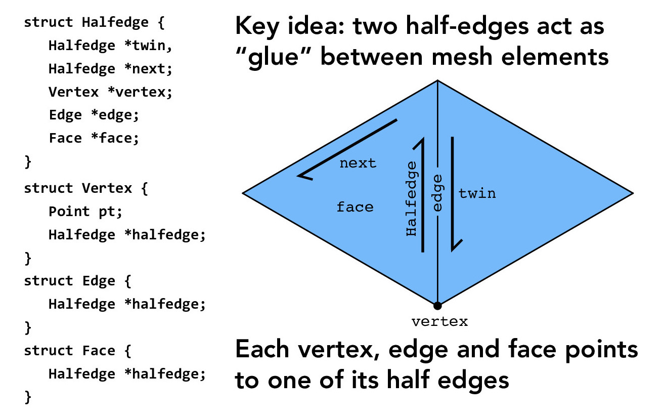
In this section, we work with the half-edge data structure, which will allow us to traverse a mesh. The core structure is outlined below.
Credit: CS184/284A Lecture 8 Slides by Ren Ng
We can improve the "look" of smooth surfaces by using Phong shading instead of flat shading. Phong shading interpolates surface normals from a face's vertex normals. These surface normals are then interpolated and normalized at each pixel to produce a smooth-looking result.
An example of flat versus Phong shading is shown below. The Phong shading is noticeably smoother.

To utilize Phong shading, we need to find the area-weighted vertex normal for each vertex. This is simply the sum of the area-weighted normals of all the faces incident to a vertex. With the half-edge data structure, we can traverse through the appropriate faces and evaluate the normal and area of each face (using cross products and norms.)
The teapot below is shown in both flat and Phong shading.

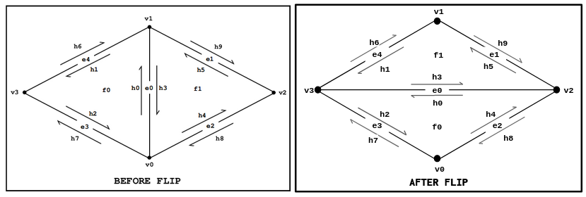
Now, we will implement features to edit a triangular mesh. The first of which will be a local remeshing operation that allows us to flip an edge.
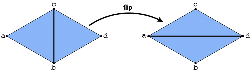
For an edge flip, no new elements are created, so we only need to reassign pointers.
To start, we can draw a before and after diagram with all the elements (i.e. halfedges, edges, vertices, faces) labeled, making sure the element labels are consistent in the pre-flip and post-flip diagrams.
Credit: CMU Graphics
Since it is easy to miss a pointer reassignment, we can start by setting all the pointers of every element in the mesh. This way, we know we have not missed anything. Afterwards, we can remove the unnecessary pointer assignments.
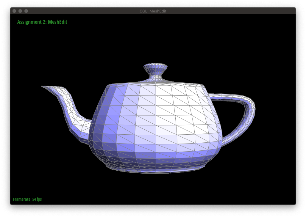
The figures below show a mesh being edited with edge flips.


Another local remeshing operation on an edge is called a split. Splitting an edge inserts a new vertex at the midpoint and connects it to the surrounding vertices.
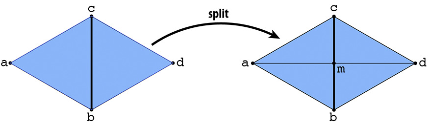
Unlike when flipping an edge, splitting an edge will create new elements. More specifically, one vertex, three edges (and thus 6 halfedges), and two faces. We will use the same implementation approach as we did in Edge Flip: draw a diagram and set all pointers.
The following figures show a mesh being edited with a combination of edge flips and splits.


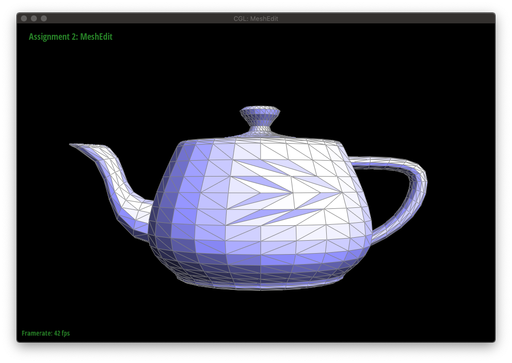
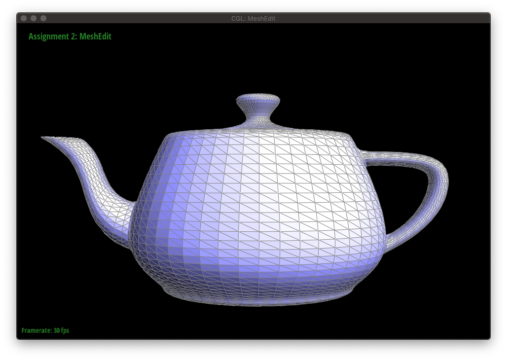
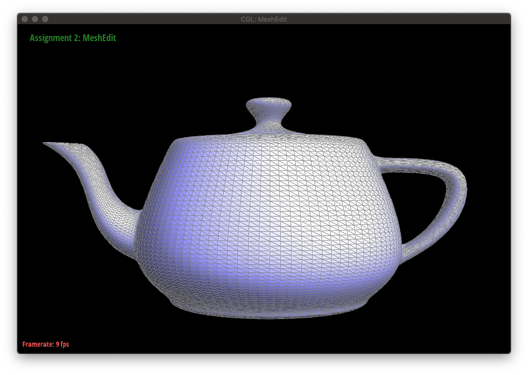
Upsampling a mesh converts a coarse polygon mesh into a higher-resolution one, which can be seen below.

In the case of loop subdivision, which upsamples a triangular mesh, there are two key ideas:
1. Subdividing each triangle into four smaller triangles, called 4-1 subdivision.
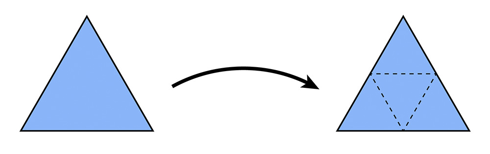
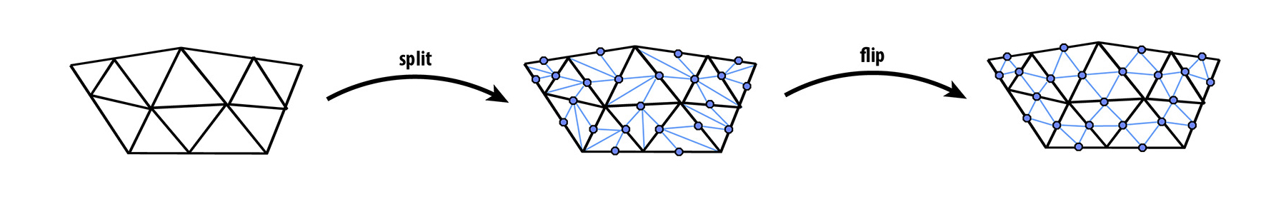
This is accomplished by first splitting each old edge of the mesh in any order, then flipping newly created edges that connect an old vertex with a new vertex.
2. Updating the vertices based on a weighting scheme
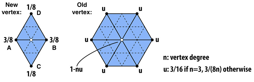
Depending on if the vertex is new or old, we use a different set of weights. In both cases, we compute the new position of the vertex based on its adjacent vertices.
The actual code implementation of loop subdivision can be divided into 5 different parts:
1. Computing the positions of the old vertices (and storing it for later)
2. Computing the positions of the new vertices (and storing it for later)
3. Splitting all old edges (in any order)
4. Flipping new edges that connect an old vertex with a new vertex
5. Updating the positions of all vertices (calculated from 1 and 2)
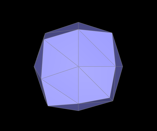
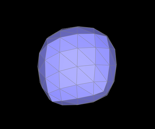
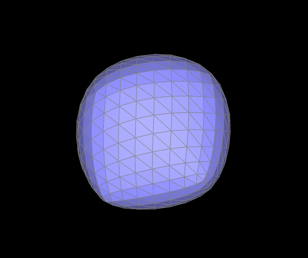
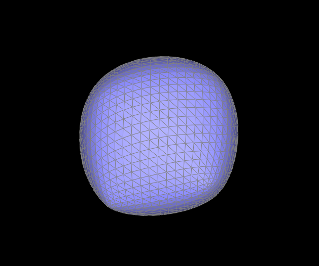
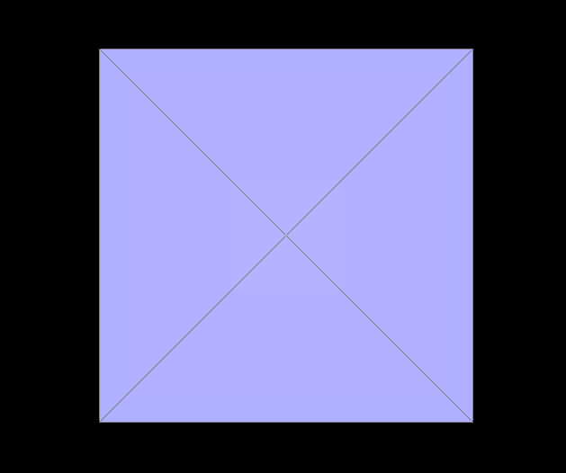
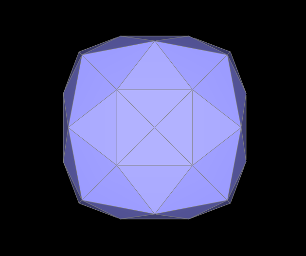
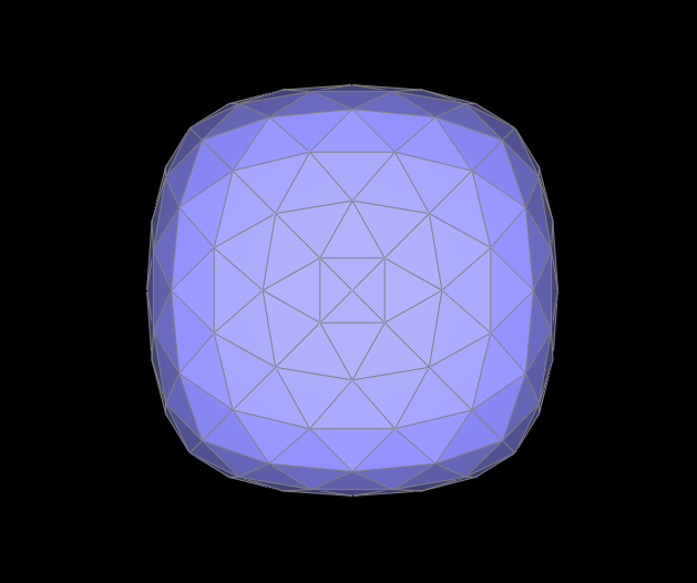
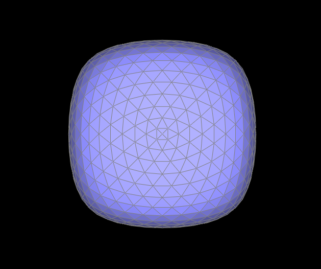
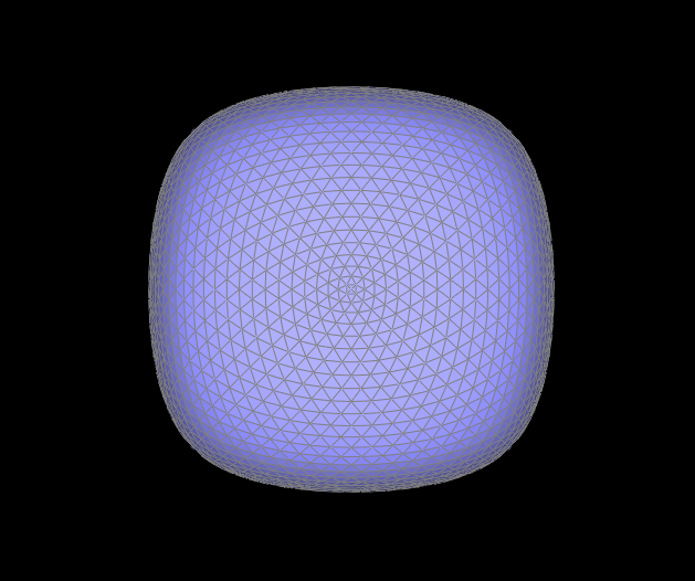
Although loop subdivision has the potential to result in smoother meshes, it is not perfect since it is highly dependent on the mesh itself. For example, the triangular mesh of the cube below is not symmetric, so upsampling via loop subdivision does not result in a symmetric mesh. Furthermore, the sharp corners and edges become rounded, and at four levels of subdivison, the mesh no longer resembles a cube.
We can fix the symmetry issue by pre-splitting edges of the mesh to make it symmetric. Below, I split some of the cube mesh's edges so that each face consists of four triangles as shown in the Level 0 figure below. Since the base mesh is symmetric, the asymmetry issue that we encountered previously is solved because upsampling on a symmetric mesh maintains symmetry at each subdivision level.
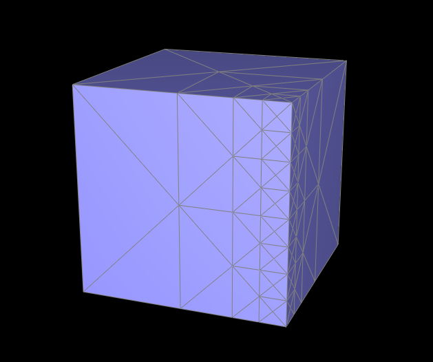
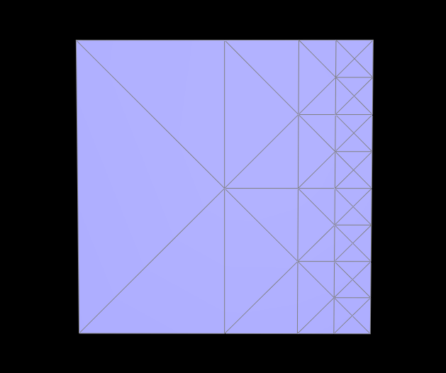
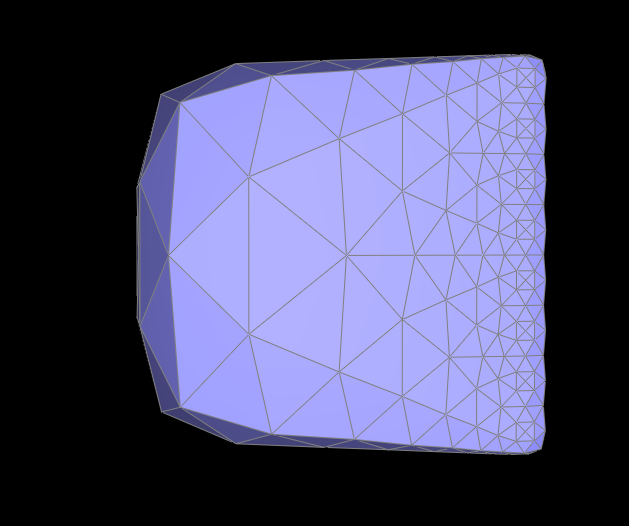
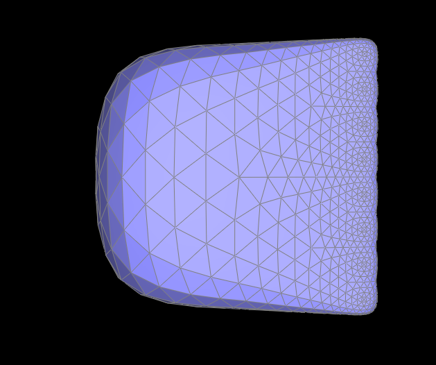
We can also alleviate the "rounding" of sharp corners and edges by adding more edges near the areas of the mesh where we would like less rounding. Having more vertices closer to each other means the effect of averaging (the vertex position weighting scheme) on a particular vertex is not as strong. In other words, the vertex is not pulled too far away from its original position because its neighboring vertices are close by.
Below, I performed many edge splits near one edge of the cube, which added many new edges and vertices. After upsampling, this edge of the cube is less round than the edges where I did not perform edge splitting.